


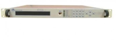
Satelitte Test Loop Translator ATLT-400 model
Overview
The Advantech Test Loop Translators ATLT-400 models are available in variety of operating bands. The units are designed for testing satellite communications links. They simulate the satellite by band-translating the uplink frequencies to the corresponding downlink frequency. A single quad band TLT unit works with four operating frequency bands – C, X, Ku and Ka.
Features
- Four Operating Bands – C, X, Ku, and Ka
- Cost effective solution
- Front panel control (local)
- Full remote control (remote)
Options
- 5 MHz external reference
- Other operating bands
Operating Bands
| Tri-Band TLT Model # ATLT- 400TB1 | ||
|
Band
|
Transmit
|
Receive
|
|
C-Band
|
5.85 - 6.425 GHz
|
3.625 - 4.200 GHz
|
|
X-Band
|
7.9 - 8.4 GHz
|
7.250 - 7. 775 GHz
|
|
Ku-Band
|
14.0 - 14.5 GHz
|
11.70 - 12.20 GHz
|
|
Ka-Band TLT Model # ATLT- 400Ka1
|
||
|
Band
|
Transmit
|
Receive
|
|
Ka-Band
|
30.00 - 31.00 GHz
|
20.20 - 21.20 GHz
|
|
Quad-Band TLT Model # ATLT- 400QB1
|
||
|
Band
|
Transmit
|
Receive
|
|
C-Band
|
5.85 - 6.425 GHz
|
3.625 - 4.200 GHz
|
|
X-Band
|
7.9 - 8.4 GHz
|
7.250 - 7.675 GHz
|
|
Ku-Band
|
14.0 - 14.5 GHz
|
11.70 - 12.20 GHz
|
|
Ka-Band
|
30.00 - 31.00 GHz
|
20.20 - 21.20 GHz
|
| Alternate Bands | ||
|
Band
|
RF Transmit Band
|
RF Receive Band
|
| C-Band | 5.85 - 6.425 GHz | 3.625 - 4.200 GHz |
| C-Band | 5.85 – 6.65 GHz | 3.450 – 4.200 GHz |
| Ku-Band | 14.0 - 14.5 GHz | 11.70 - 12.20 GHz |
| Ku-Band | 14.0 - 14.5 GHz | 12.25 - 12.75 GHz |
| Ku-Band | 13.75 - 14.5 GHz | 12.0 - 12.75 GHz |
| Ku-Band | 13.75 - 14.5 GHz | 10.95 – 11.70GHz |
| DBS-Band | 17.35 – 18.1 GHz | 11.7 – 12.50GHz |
| Ka-Band | 29.50 - 30.00 GHz | 19.20 – 19.70 GHz |
| Ka-Band | 29.50 - 30.00 GHz | 19.70 – 20.20 GHz |
| Ka-Band | 29.50 - 31.50 GHz | 20.50 – 21.50 GHz |
Technical Specifications
|
RF Output
|
|
| Frequency range |
(See table on front page)
|
| Input impedance |
50
|
| Input VSWR | 1.5:1 max over any operating band |
| Max input level |
+10 dBm
|
|
Output impedance
|
50
|
|
Output VSWR
|
1.5:1 max over any operating band
|
|
Conversion Parameters
|
|
| Conversion Gain |
-35 dB max
|
| Gain adjustment |
50 dB
|
| Attenuator step size |
1 dB
|
|
Gain flatness
|
2.0 dB P-P max.
0.8 dB P-P max. over any 40 MHz |
|
Gain stability
|
±0.75 dB/15°C max. 0°+55°C
|
|
Spurious
|
-40 dBc In-band
-50 dBm Out-of-band |
| Group delay (over 40 MHz) Linear Parabolic Ripple |
0.02 ns/Hz 0.003 ns/MHz2 1 ns p-p |
|
Phase noise
10 Hz 100 Hz 1000Hz 10 kHz 100 kHz 1 MHz to 5 MHz |
-35 dBc -65 dBc -75 dBc -85 dBc -95 dBc -95 dBc |
| Controls & Indicators | |
| Band select | |
| Attenuator select | |
| Local/Remote | |
| Mute/ Unmute | |
| Total time is use | |
|
Reference
|
|
| External Reference |
5 MHz (10 MHz option)
|
| External ref. input level |
0 dBm ± 5 dB
|
| Internal reference stability |
+/-2 x 10-8 / day
|
|
Aging
|
+/-1 x 10-7 / year
|
| Mechanical | |
| Dimensions | Width 19” (482.6 mm) |
| Height 1U 1.75” (44.5 mm) | |
| Depth 20” (508 mm) | |
| Power Supply | |
| Voltage | 90 – 265 VAC (47 – 63 Hz) |
| Power | 20W |
| Connector | IEC 603320 10A |
|
Monitor and Control
|
|
| RS 485 |
DB9
|
| RS232 |
DB9
|
| Discrete |
DB9
|
|
Environmental
|
|
| Operational |
0°C to +50°C standard
|
| Storage |
-55°C to +85°C
|
| Humidity |
Non-condensing
|
| Altitude |
3,000m AMSL
|


